A few days ago, I decided it was time for a “bigger” display.
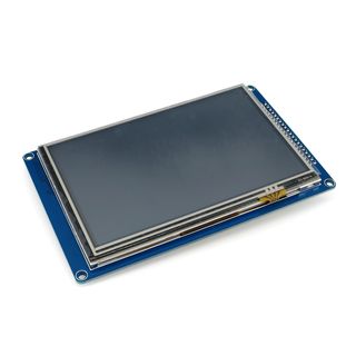
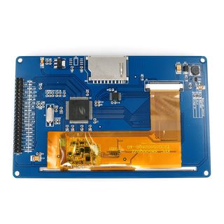
I did find a 5″ screen with 480×800 resolution, with an SSD1963 controller.
This screen not only has the advantage of being bigger than my previous one (ILI9488 – 3.5″ – 320×480 – SPI),
but also comes with a higher resolution, and does have a parallel interface. (so screen drawing/refresh will be faster)
I will have room to fit 16 icons in one column (instead of 2 rows of 8 icons).
This will not be only results in an overal better view, but I will also have 2x 14 icons in one switch-panel (instead of 2x 6)
and also the locomotive-filterlist will contains more items (2 x 14 instead of 2 x 6)
I need to do a bit of redesign, but the logic itself stays the same, so this should be easily and fast integrated …


*UPDATE*
This weekend I did spend some time to attach the new screen onto the LilyGo TTGO T8 (main controller)
This screen uses a lot more connections (8-bit parallel instead of SPI), so I knew from the beginning that getting everything connected,
would be a nice challenge 🙂
| # pins | Description |
|---|---|
| 13 | SSD1963 TFT controller |
| 2 | I2C bus (for buttons) |
| 4 | SPI bus + CS for SD-Card |
| 2 | RX/TX |
| 1 | Battery level |
So, we need 21 pins, for basic, functionality !
I also need a way to connect the TFT touch-interface, the joystick-module, and the rotary encoder. In my first setup this needed 7 extra pins.
But the ESP32-modules only have 21 pins, and I don’t want to change to another controller, or add a second controller. (for auto-firmware updates,
this would make things really complicated !)
But I did find a way around all this !
– Joystick module can be connected to I2C via an ADS1115, a 4-channel ADC.
– Rotary encoder can also be connected to I2C via an I2C Encoder mini.
– the CS-pin of the TFT screen can be tied to GND instead of a GPIO-pin
– We only need one extra pin for the CS-connection of the touch-panel.
(this is an SPI-controller – XPT2046, and can use the same SPI bus for communication)
So, with some clever “thinking”, I just have enough GPIO-pins to connect all peripherals and use the 8-bit parallel SSD1963 5″ TFT screen 🙂
And in case we need to add something extra, I need to make sure that I can make a connection over I2C …
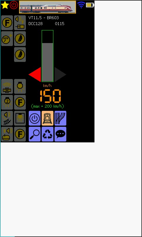
In the next picture, you can see the difference between the old ILI9488 and the new SSD1963. The white area is the complete new resolution/screen-space, while in the upper-left corner, you can see LocoMotion “running” with the old (lower) resolution …
(and yes, even “screencapture” still works over the 8-bit parallel connection !)
