In our new cabinet, we have about 3 large glass shelves, each 90 cm x 90 cm. The idea came to mind to put some “big” locomotives on these shelves. So, I started looking around, and noticed that “gauge 1” or “LGB” or “G-scale” locomotives where in fact “to expensive” to just use is as “decoration”. Why buy a complete engine with all electronics in it and a motor, if you are only going to use it as a static model ? So, I looked a bit further, and I found some interesting kits in scale 1/35th, from Trumpeter. One of these kits is a BR52, which, once finished, will measure about 89 cm in length. If I put this locomotive diagonally on the shelve, I will even have about 30 centimeters left 🙂 After a while, the idea became even “bigger”: Why only put a locomotive on rails in the cabinet ? Why not create a complete diorama around it ? While looking on Ebay for a BR52 for a reasonable price, I stumbled upon an “after-market” product for this building kit. LionRoar does offer a PE-set (photo-etched parts), to replace some of the original “plastic” parts of the original Trumpeter kit, to make the locomotive look even more detailled and realistic. So, I ordered a BR52 from Trumpeter, and … the upgrade-kit from LionRoar 🙂
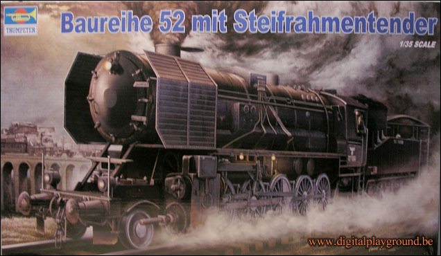
The original trumpeter kit
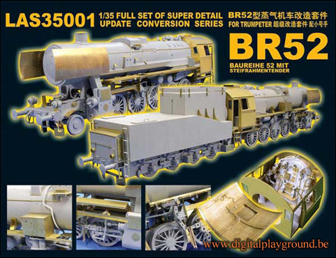
The LionRoar upgrade kit
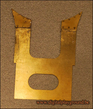
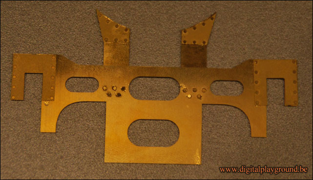
Some PE parts (Friday – october, 16th – 2009)
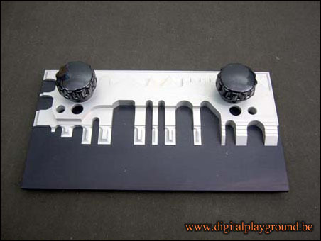
The LionRoar PE-set already arrived, but the Trumpeter BR52 kit is not arrived yet … Because I never worked with PE before, I decided to give this already a try 🙂 First of all, there are a lot of PE-parts in this set, which needs to be bended is certain angles. The PE pieces are really thin (and I mean, really, really, really thin !), so it’s nearly impossible to do this by hand, without damaging the parts. But, there is a piece of tool, specially made for this type of bending 🙂 It’s called a “Hold and Fold”. (which I ordered together with my PE set) The idea is pretty straight-forward, put your pieces between the “Hold and Fold”, and use the included special bending piece, to get everything done as smooth as possible.
The actual “Hold and Fold” tool
So, I was ready and up for the “challenge” … Here are some of the first results …The first piece is soldered with a special soldering-paste (melting point = 179 degrees Celcius). Everything works fine, but it’s actually not that easy to solder these parts together and the pieces are really getting dirty. After this, I did put the parts in my ultrasonic cleaner, which erased all the dirt from the piece, and made it shinny again !
First piece.
These pieces are glued together with contact super-glue. The completed piece you see here above, consists of about 31 PE pieces, some about 1 mm in diameter !
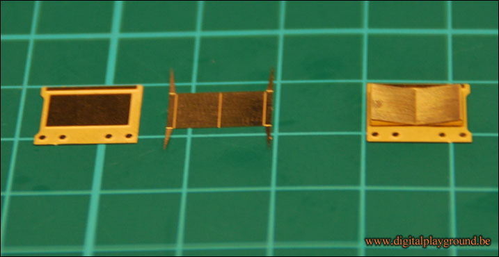
Next, I was up to a “test” in bending the PE (the 2 above pieces only contained “flat” PE-pieces. On the left, you see 2 pieces, on the right you see these 2 pieces “bended and glued” together. The middle piece is bended in some sort of a “book-shape”, where the 3 points/triangles, form the back of the book (as you can see on the right) I must say, after all, this is a complete new experience for me, but I like it 🙂 My wife is getting nervous if she see such small pieces, but I really enjoy it, it actually makes me calm …
The actual building of the BR52 (Saturday – november, 21th – 2009)
The BR52 kit from Trumpeter finally arrived yesterday. (After waiting for more then a month to receive it from China) … Ooh well, I can’t complain, the kit was actually cheap, compared to (E-)shops within Europe, and I had enough other things to do in the meantime. And on the other hand, even a second BR52 is on it’s way to Belgium 🙂
Enough smalltalk, onto some pictures of my first progression …
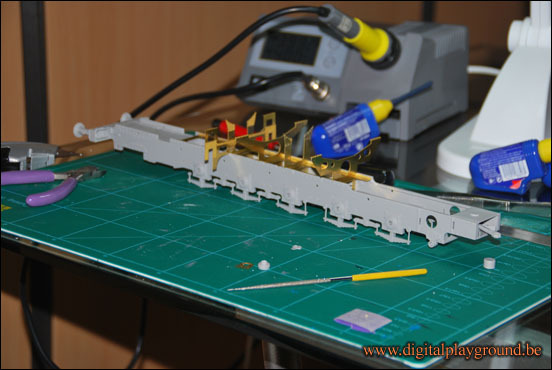
Step one and two of the original instructions are done, I’m currently busy with step 3. The whole locomotive exists out of 26 steps, and another 5 steps are needed to build the tender. On the other hand, while building the original kit, I also need to follow the steps for the PE. I’m currently finishing step 1 out of 10.
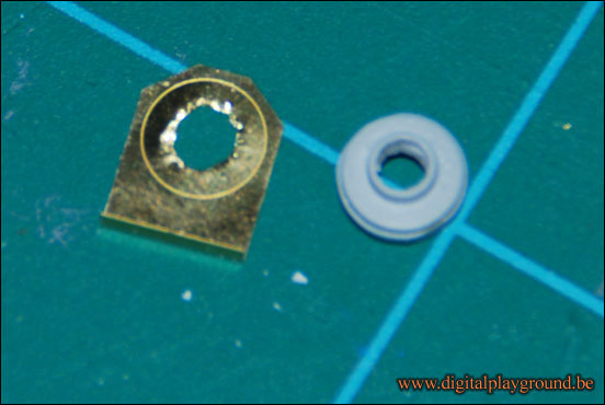
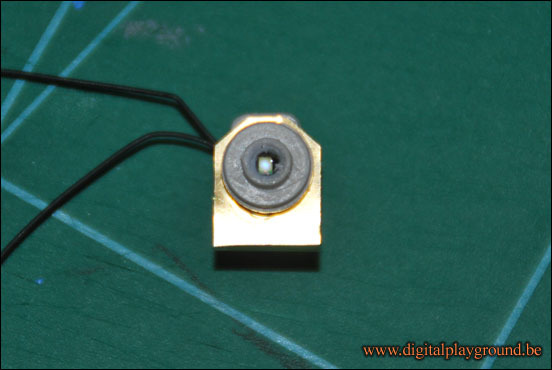
I wanted to be sure that SMD LEDs would fit, so I started some “modifications” on some parts 🙂
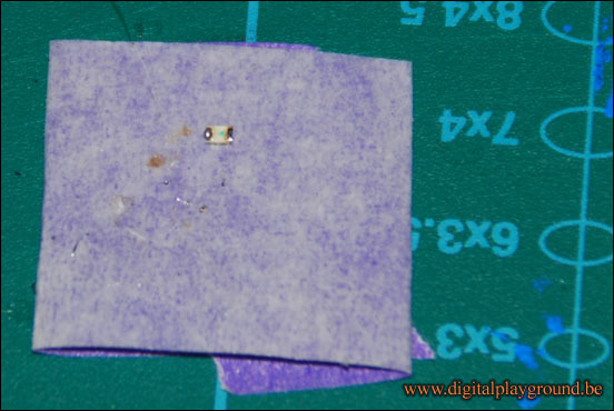
I placed a small piece of tape, doublesided on my cutting board, and placed an SMD LED firmly onto this tape, to easen-up soldering of the wires.
The “white square” in the middle of the light enclosure, is the actual SMD LED in place.
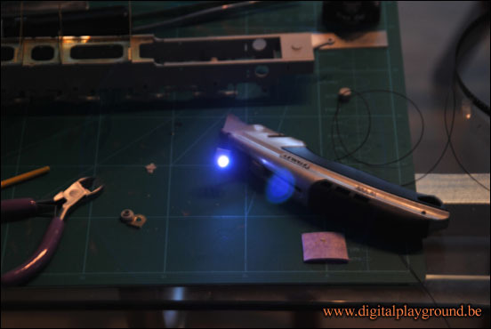
The LED … illuminated !
“Chassis” done (Tuesday – november, 24th – 2009)
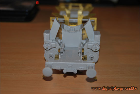
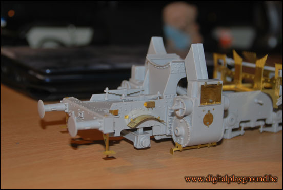
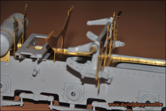
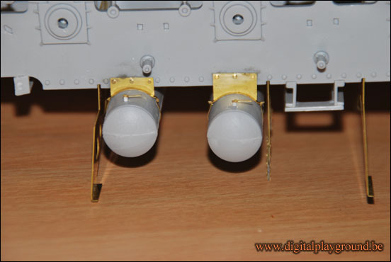
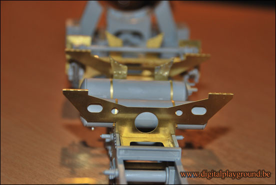
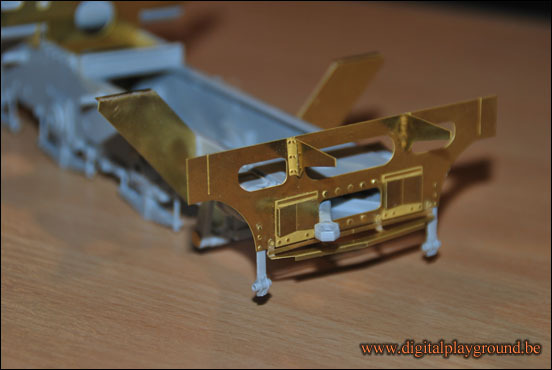
The chassis of the BR52 is mostly done. (first four steps in the building instructions) So, time to paint this “part”, but before painting I would like to show you some detailed pictures. (they are taken in order from the front to the back)
Front view.
Another frontview, but taken from an angle.
Doesn’t all these PE parts look good ?
The small handles on the tanks consists each out of 4 pieces !
Lenght view.
Back view.
Tonight I hope to paint the chassis in red 🙂
“Chassis” done (Tuesday – november, 30th – 2009)
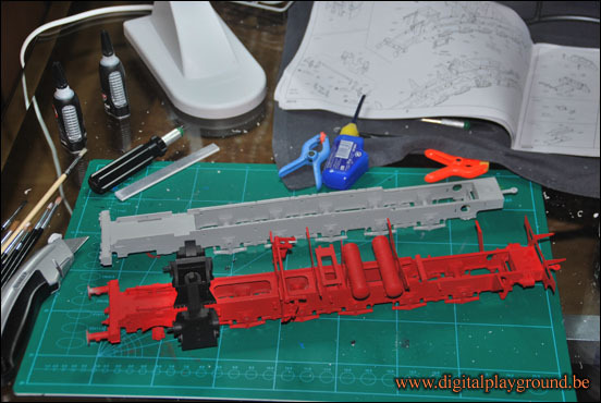
Last Wednesday, I painted the chassis in red (and black). Because of my illness, I was unable to take pictures and put them here online. Today step 1 and 2 are finished of the second BR52, and while taking pictures of it, I did take some time to take an extra picture. Chassis of BR52 “number one” and chassis of BR52 “number two”, on the same picture, as a sort of proof that we really are “busy” with 2 of these “monsters” 🙂
Side by side 🙂
To be continued …
